
Custom 5-Phase Stepper Driver for Optical Turntable Control
When Test Equipment Outlives Its Documentation
Background
Fire beam detectors are a common solution for protecting large open spaces — warehouses, atriums, aircraft hangars — where point detectors would be impractical. They work on a simple principle: a transmitter projects an infrared beam across the space to a reflector, and any sustained obscuration of that beam triggers an alarm. Simple in principle, but their installation relies on precise optical alignment between transmitter and reflector, sometimes across distances exceeding 100 metres.
This alignment tolerance is not left to guesswork. The European standard EN 54-12:2015 defines a specific test procedure — clause 4.3.3, Tolerance to beam misalignment — to verify that a detector can maintain correct operation within its declared angular range and reliably trigger an alarm once that range is exceeded.
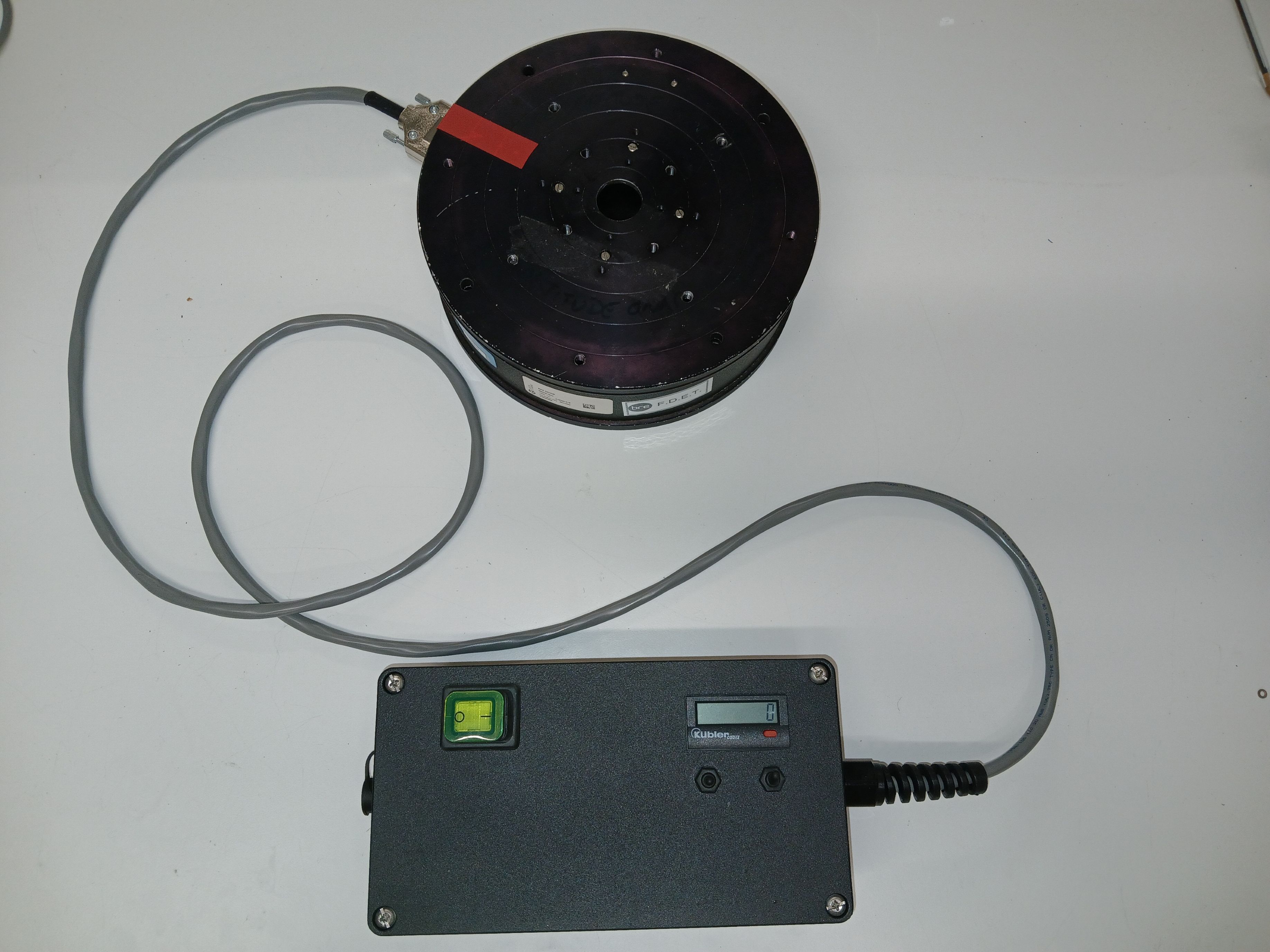
The test procedure is deliberate and methodical. The detector under test is mounted on a precision turntable, with its reflector fixed at the far end of a purpose-built optical runway, outdoors. The turntable rotates the detector about a vertical axis — and later a horizontal axis — at an extremely slow rate of 0.3° per minute. At the manufacturer's declared maximum misalignment angle, a calibrated 6 dB optical attenuator is introduced into the beam path. The detector must respond with an alarm signal within 30 seconds. The smallest angle at which a fault or alarm signal is emitted is recorded. The full procedure is repeated in the counter-clockwise direction, and then about the horizontal axis.
To put 0.3° per minute into perspective: a full 360° rotation would take twenty hours. This is not a test that rewards imprecision in motor control.
The turntable itself is a precision optical instrument from Ealing Electro-Optics, most likely manufactured in the late 1980s. Ealing Electro-Optics — based in Watford, England — was a well-regarded scientific optics and instrumentation manufacturer before being acquired by Coherent Inc. in 1997. The manufacturing operations subsequently changed hands to Davin Optronics in 2001, and the catalog business was ultimately sold to Hyland Optical Technologies in 2013. By the time I attempted to contact Coherent to retrieve any historical documentation on this particular unit, the institutional memory of a turntable from the previous decade had long since dispersed across three ownership changes. Unsurprisingly, the call did not yield a datasheet.
It is worth noting an oddity in the system configuration: the test is conducted outdoors, across a 100-metre optical runway exposed to the elements — yet the precision optical turntable at its heart carries no weatherproofing rating. The controller enclosure, by contrast, was specified as weatherproof, built into an IP68-rated housing and operated to IP65. The turntable is managed accordingly: it is set up for the test and recovered. Not elegant, but it has worked for decades.
The turntable is driven by a five-phase stepper motor. This motor topology is less common than the ubiquitous two-phase stepper, but offers smoother motion at low speeds, reduced vibration, and finer angular resolution — well suited to a mechanism that needs to rotate at fractions of a degree per minute. The motor had been in service for many years, driven by a custom analogue controller designed in-house roughly two decades earlier.
In May 2024, a fault report was logged: the test rig was no longer measuring reliably. The angle readout was only registering rotation when the operator applied direct physical pressure to the display with a finger. The rig was flagged out of service pending investigation.
Assessment
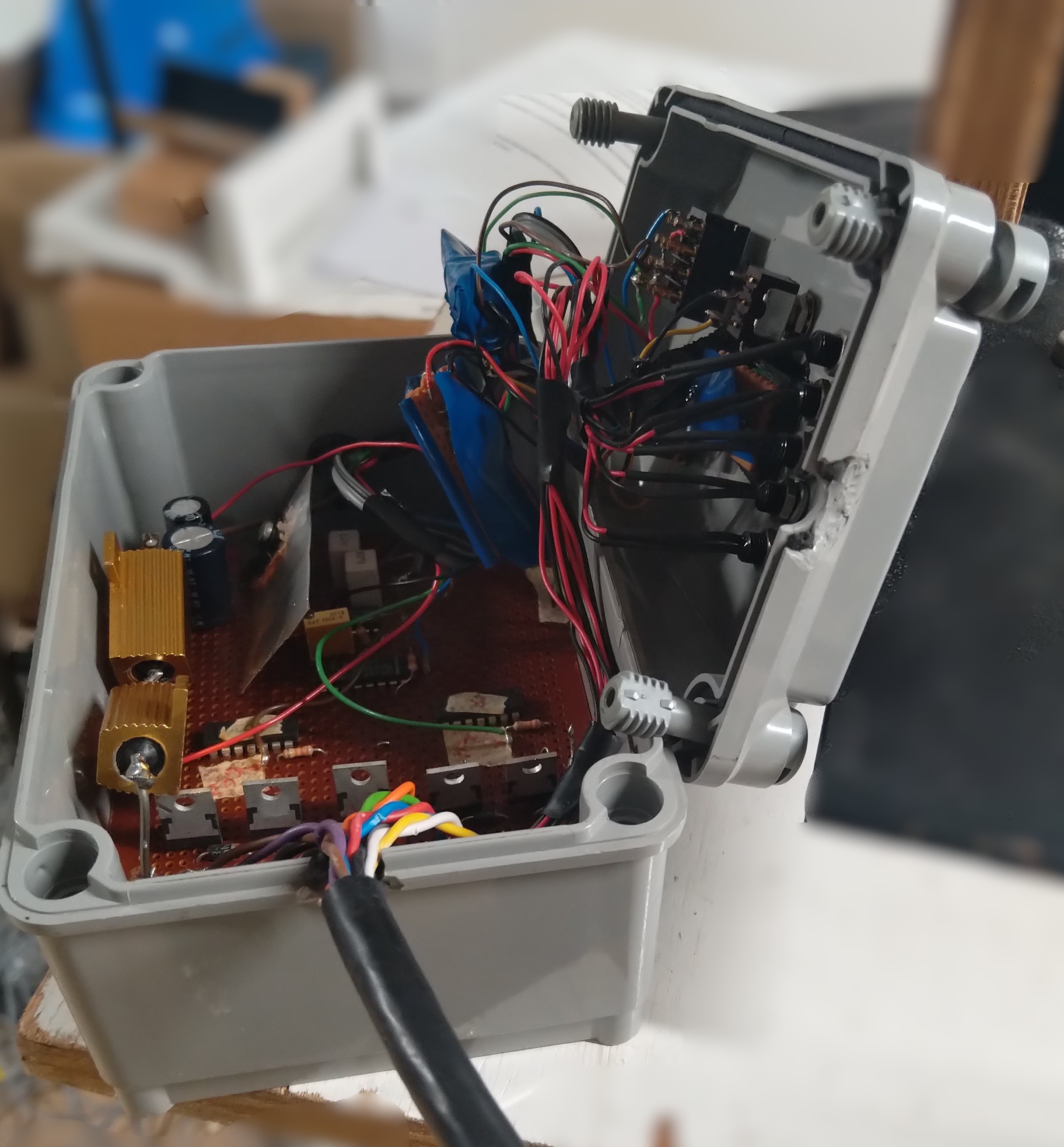
The first step was a physical inspection of the controller enclosure. What I found inside gave pause.
The electronics were built on Veroboard — entirely acceptable for a proof of concept or a one-off prototype, but not for a piece of calibration equipment expected to remain in active service for decades. The wiring had accumulated into a dense, unsupported tangle that made circuit tracing difficult and fault-finding unnecessarily time-consuming. The power stage thermal management consisted of a small aluminium plate bonded directly to the MOSFET with adhesive — an approach that offered minimal heat dissipation under any sustained load and no mechanical security whatsoever. The cable entry, rather than being fitted with a proper IP-rated gland, had been improvised using a groove cut into the enclosure wall with a pair of pliers. Whatever IP rating the housing had originally carried was, at that point, a matter of optimism rather than engineering.
The immediate fault — the pressure-sensitive display — was symptomatic of a broader problem: years of reactive patching rather than structured maintenance had brought the system to a point where its ability to produce reliable, defensible calibration data could no longer be assumed.

Fortunately, the engineer who had originally designed the controller some twenty years earlier was still a colleague, and was willing to retrieve and provide the original schematic. This was invaluable — it allowed a full review of the circuit architecture, component selection, and I/O configuration, and formed the documented starting point for the redesign. He provided that schematic not long before he passed away. His contribution to this project, and to the facility more broadly, deserved a proper conclusion: equipment rebuilt to a standard that will outlast us both.
I took the decision to replace the control electronics entirely. Patching an ageing assembly with incomplete documentation and hoping for the best is not a position you can defend when the equipment underpins UKAS-traceable calibration work.
Design
The redesign was shaped by two practical constraints that governed every decision.
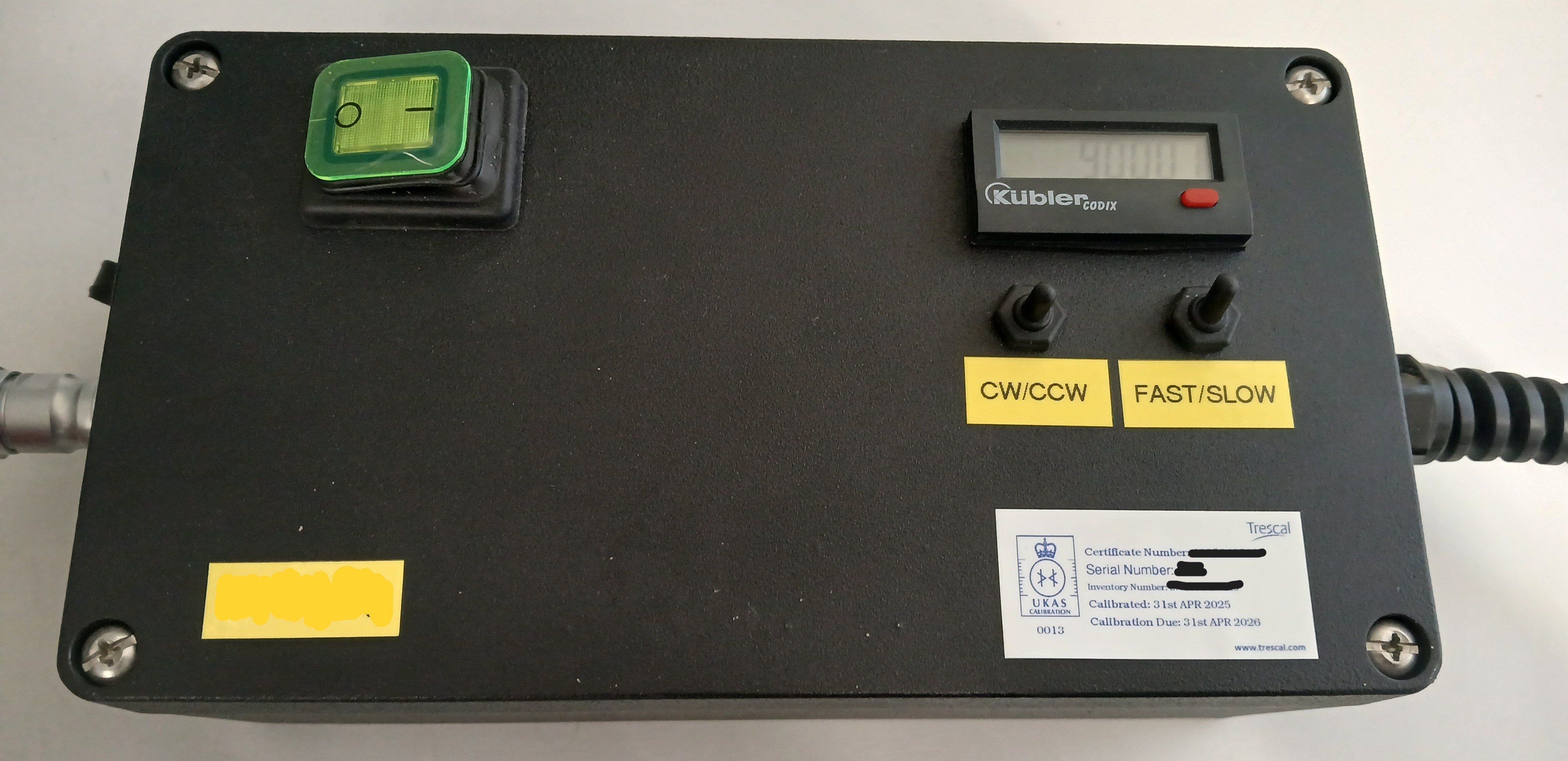
The first was continuity of operation. The technicians who operate this test rig are specialists in fire detection, not electronics. Presenting them with a controller that behaved differently from the one they had used for twenty years would have introduced unnecessary risk of procedural error. The aim was to replicate the user experience of the original — the same controls, the same indicators, the same logical behaviour — while replacing everything underneath with a properly engineered implementation.
The second constraint was preservation of the fundamental technical approach. The original design was fully analogue, and that was maintained. Introducing a microcontroller would have required firmware development, version control, and a software qualification process that was out of scope for the project at the time. The analogue architecture, properly implemented, was entirely fit for purpose and allowed all existing test procedures to remain valid without modification.
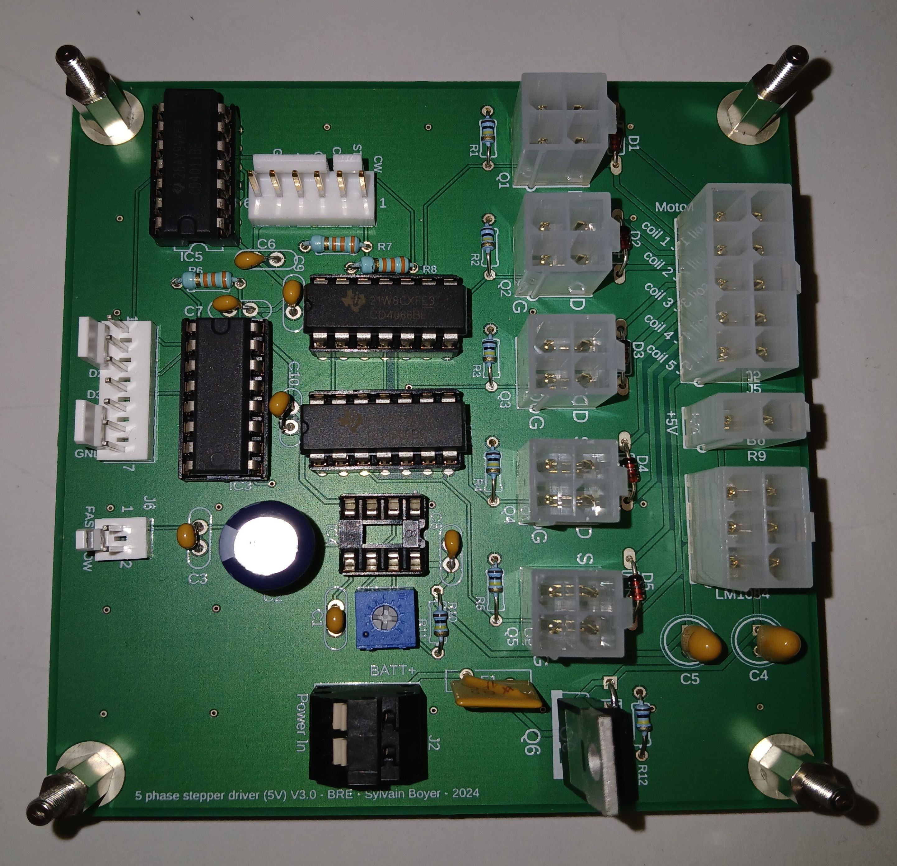
Five-phase stepper drivers are not commodity items. The motor topology is relatively uncommon outside of precision industrial applications, and at the time of the project only one or two commercial driver solutions existed at a suitable specification — both at a price point difficult to justify for a single piece of in-house test equipment. A custom solution was the practical path.
The design followed a conventional engineering workflow. The original schematic was reviewed and used as the functional baseline, and several improvements were incorporated from the outset. A reverse polarity protection circuit was added. The N-MOSFETs driving each motor coil, along with the LM1084 voltage regulator, were relocated from the PCB and mounted directly on the outer face of the heavy aluminium enclosure — allowing the enclosure itself to serve as the heatsink, eliminating the thermal compromise of the original design entirely.
The power stage and sequencing logic were modelled in LT-SPICE to validate the design before committing to layout — verifying switching behaviour, thermal margins, and the five-phase drive waveforms in simulation rather than on the bench.
*** LT Spice model picture ***
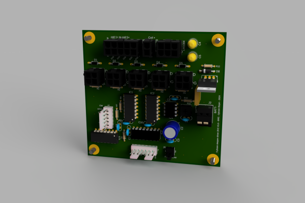
Two PCB revisions were produced, both going directly to manufactured PCB from the outset, keeping the development path clean and the documentation traceable. Connectors were selected with assembly and long-term maintenance in mind — a detail that sounds mundane until the next engineer has to work on the unit. The electrical harness was designed to be assembled independently from the PCB, simplifying both initial build and any future intervention. The user interface was upgraded to an illuminated power switch and an industrial step counter with reset function — functionally familiar to existing operators, but built to a standard appropriate for field calibration equipment.
On the mechanical side, the enclosure modifications were fully documented with technical drawings and subcontracted to Hartom Fabrication for precision metal cutting. This ensured the IP65 cable glands, panel-mount connectors, and MOSFET mounting provisions were machined to specification rather than improvised — a deliberate break from the approach taken in the original build.
*** 3D CAD picture ***
Outcome
The rebuilt controller has been fully integrated with the test rig and has completed UKAS calibration — the United Kingdom Accreditation Service standard underpinning the traceability of measurements made on accredited test equipment. The facility is back in service.
From a technical standpoint, the outcome is straightforward: a critical piece of calibration infrastructure that was at risk of producing unreliable data now meets the engineering standard it should always have been held to. The turntable rotates at the correct speed, the angle readout functions without manual intervention, and the enclosure maintains its IP rating under normal operating conditions.
The broader point is perhaps worth reflecting on. The original design was not the product of poor engineering judgement — it was the work of an experienced engineer solving a real problem with the tools and time available at the time. What the situation illustrates is the long-term cost of deferred maintenance and the absence of formal engineering review cycles for in-house test equipment. Calibration rigs and jigs tend to sit outside the asset management processes that govern commercial products. They accumulate patches, lose their documentation, and quietly drift from their original specification over years and decades.
In this case, the fault presented as a minor operational nuisance. The risk behind it was rather less minor: calibration data generated by equipment operating outside its verified specification, used to certify life-safety products.
The rebuilt controller is documented, traceable, and engineered to a standard that will support the next twenty years of service — with considerably less creative wiring.